Wenzhou Laike Electric Co.,Ltd.
Product Details
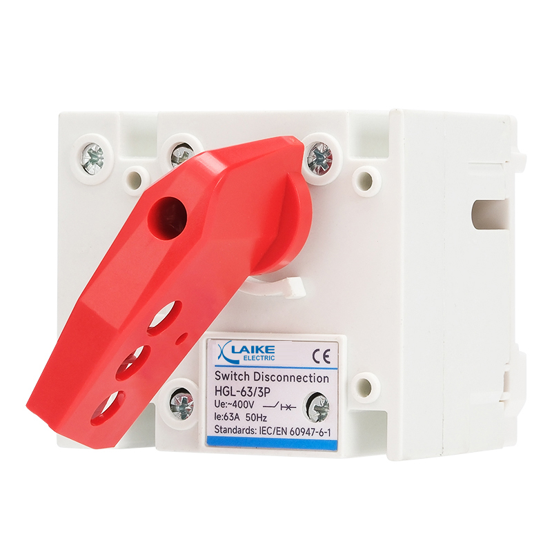
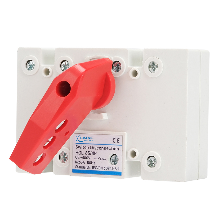
HGL series load-isolation switch changeover Switch is applied in the circuit of AC 50 HZ,rated voltage 400V or below Rated current:16A-3150A Pole:3P,4P
Product Summary
HGL series load-isolation switch is applied in the circuit of AC 50 HZ,rated voltage 400V or below,and rated current to Max 16A~3150A. It is used to connect and break circuit by not-frequent manual operation.In addition, product with 690V is only used to electrical isolation.
Operating Conditions
1.Altitude not more than 2000m.
2.The range of ambient temperature is from 5℃ to 40℃.
3.Relative humidity not more than 95%.
4.The environment without any explosive medium.
5.The environment without any rain or snow attacking.
Note:If the product is expected to be used in the environment where temperature is over+40℃ or below -5℃ to 40℃,uses shall tell it to the manufacture.
Structure Feature
1.The switch adopts the acceleration closing mechanism in which the spring energy storage is in place and the quick instantaneous release,and the contact structure of the parallel double-breakpoint at the same time,which greatly improves the electrical performance and mechanical performance of the switch.
2.The switch conductive parts are installed in an insulating base made of glass fiber reinforced unsaturated polyester molding compound;the operation mode is :manual operation handle operation,high dielectric property,protection ability and reliable operation safety.
3.The switch has 3 poles,4poles(3 poles+adjustable neutral pole).
Technical Parameter
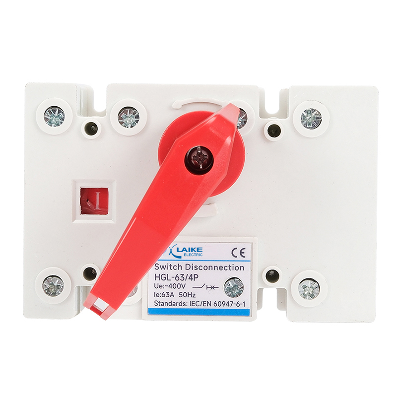
1.The front side of the switch is provided with a marking window to indicate the on/off state of the contact;the rear observation window can be provided as needed,and the on-off state of the contact can be directly observed to ensure the reliability and safety of the switch operation.
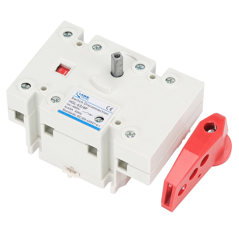
2.The operation handle can be directly installed in switch operation(referred to as the operation inside the cabinet), or can be operated outside the cabinet door by the extension shaft(referred to as the operation outside the cabinet),providing convenient operation.
3.The normally open normally closed auxiliary contact and the installation of the dedicated backplane and the front panel rear writing can be provided as needed to meet various needs of uses.
4.When the segment is”0”,two handles can be used to lock the handle to prevent misoperation.
Model and meaning


Technical data
Table 1
| ltem | Date | |||||||||
| Conventional thermal current (A) | 63A | 100A | 160A | 250A | ||||||
| Rated current In(A) | 40 | 63 | 80 | 100 | 125 | 160 | 200 | 250 | ||
| Rated insulation voltage Ui(V)(installation type IV) | 690 | 690 | 690 | 690 | 690 | 690 | 690 | 690 | ||
| Dielectric strength (V) | 5000 | 5000 | 5000 | 5000 | 5000 | 5000 | 5000 | 5000 | ||
| Rated surge-resistant voltage Uimp kV(installed category IV) | 6 | 6 | 6 | 6 | 6 | 6 | 6 | 6 | ||
| Rated working current le(A) | 400V | AC-21B | 40 | 63 | 80 | 80 | 125 | 160 | 200 | 250 |
| AC-22B | 40 | 63 | 80 | 80 | 125 | 160 | 200 | 250 | ||
| AC-23B | 40 | 50 | 80 | 80 | 125 | 160 | 200 | 250 | ||
| 660V | AC-21B | 40 | 50 | 80 | 80 | 125 | 160 | 200 | 250 | |
| AC-22B | 32 | 32 | 50 | 50 | 125 | 160 | 160 | 160 | ||
| AC-23B | 25 | 25 | 40 | 40 | 80 | 80 | 100 | 125 | ||
| Motor power P(KW) | 400V | 18.5 | 25 | 40 | 40 | 63 | 80 | 100 | 132 | |
| 660V | 22 | 22 | 33 | 33 | 75 | 75 | 90 | 110 | ||
| Rated short-time withstand current Icw(kA Rms)0.1s/1s | 2 | 2 | 2 | 2 | 8 | 8 | 12 | 12 | ||
| Rated breaking capability Icn(A Rms)AC23400V | 320 | 504 | 640 | 800 | 1000 | 1000 | 1600 | 1600 | ||
| Rated making capability Icm(ARms)AC23400V | 400 | 630 | 800 | 1000 | 1250 | 1600 | 2000 | 2500 | ||
| Rated short-current making capability Icm (kA peak value) | 2.84 | 2.84 | 2.84 | 2.84 | 13.6 | 13.6 | 17 | 17 | ||
| Mechanical durability 400V | 1700 | 1700 | 1700 | 1700 | 1400 | 1400 | 1400 | 1400 | ||
| Electrical durability 400V | 300 | 300 | 300 | 300 | 200 | 200 | 200 | 200 | ||
| Operation moment(Nm) | 1.2 | 1.2 | 1.2 | 1.2 | 6.5 | 6.5 | 10 | 10 | ||
Table 2
| Item | Date | |||||||||||
| Conventional thermal current (A) | 400A | 630A | 1600A | 3200A | ||||||||
| Rated current In(A) | 315 | 400 | 500 | 630 | 1000 | 1250 | 1600 | 2000 | 2500 | 3200 | ||
| Rated insulation voltage Ui(V)(installation type IV) | 1000 | 1000 | 1000 | 1000 | 1000 | 1000 | 1000 | 1000 | 1000 | 1000 | ||
| Dielectric strength (V) | 8000 | 8000 | 8000 | 8000 | 10000 | 10000 | 10000 | 10000 | 10000 | 10000 | ||
| Rated surge-resistant voltage Uimp kV(installed category IV) | 6 | 6 | 6 | 6 | 6 | 6 | 6 | 6 | 6 | 6 | ||
| Rated working current le(A) | 400V | AC-21B | 315 | 400 | 500 | 630 | 1000 | 1250 | 1600 | 2000 | 2500 | 3200 |
| AC-22B | 315 | 400 | 500 | 630 | 1000 | 1250 | 1600 | 2000 | 2500 | 3200 | ||
| AC-23B | 315 | 400 | 500 | 630 | ||||||||
| 660V | AC-21B | 315 | 400 | 400 | 500 | 1000 | 1000 | 1600 | 2000 | 2500 | 2500 | |
| AC-22B | 315 | 315 | 315 | 315 | 800 | 800 | 800 | 1000 | 1250 | 1600 | ||
| AC-23B | ||||||||||||
| Motor power P(kW) | 400V | 160 | 220 | 280 | 315 | 560 | 560 | 560 | 710 | 710 | 710 | |
| 660V | 185 | 185 | 185 | 185 | 475 | 475 | 475 | 750 | 750 | 750 | ||
| Rated short-time withstand current Icw(kA Rms)0.1s/1s | 25 | 25 | 25 | 25 | 50 | 50 | 50 | 50 | 50 | 50 | ||
| Rated breaking capability Icn(ARms)AC23400V | 2520 | 3200 | 4000 | 5040 | 3000 | 3750 | 4800 | 6000 | 7500 | 9450 | ||
| Rated making capability Icm(A Rms)AC23400V | 3200 | 4000 | 5000 | 6300 | 3000 | 3750 | 4800 | 6000 | 7500 | 9450 | ||
| Rated short-current making capability Icm (kA peak value) | 40 | 40 | 40 | 40 | 70 | 70 | 70 | 105 | 105 | 105 | ||
| Mechanical durability 400V | 800 | 800 | 800 | 800 | 500 | 500 | 500 | 300 | 300 | 300 | ||
| Electrical durability 400V | 200 | 200 | 200 | 200 | 100 | 100 | 100 | 100 | 100 | 100 | ||
| Operation moment (Nm) | 14.5 | 14.5 | 14.5 | 14.5 | 37 | 37 | 37 | 60 | 60 | 60 | ||
Operation mode
1.Direct operation: The handle is installed in the middle of the switch.
2.Operation outside the board: The handle is installed outside the door off distributing board.

Overall and mounting dimensions(mm)
Load isolation switch side operation load isolation switch of HGL-63A-100A


| Specification | Overall Dimensions | Installation Dimensions | |||||||
| A | B | C | D | a | b | Φc | d | ||
| HGL-100 | 13 | 85 | 125 | 68 | 27 | 54 | 58 | 4.5 | 7 |
| 14 | 109 | 125 | 68 | 27 | 54 | 58 | 4.5 | 30 | |
Outline and Installation Dimensions of HGL-160-1600A


| Model | Overall Dimensions | Mounting Dimensions | Terminal Dimensions | |||||||||||||
| A | B | C | D | H | a | b | Φc | d | e | R | S | T | Y | M | ||
| HGL-160 | 13 | 140 | 135 | 92 | 36 | 85 | 120 | 65 | 5.5 | 27 | 85 | 20 | 10 | 3.5 | 25 | 8 |
| 14 | 170 | 135 | 92 | 36 | 85 | 150 | 65 | 5.5 | 27 | 85 | ||||||
| HGL-250 | 13 | 180 | 170 | 102 | 50 | 110 | 160 | 90 | 5.5 | 35 | 115 | 25 | 15 | 3.5 | 25 | 10 |
| 14 | 230 | 170 | 102 | 50 | 110 | 210 | 90 | 5.5 | 35 | 115 | ||||||
| HGL-400 | 13 | 230 | 240 | 135 | 65 | 160 | 210 | 140 | 7 | 50 | 145 | 32 | 17 | 5 | 37 | 10 |
| 14 | 290 | 240 | 135 | 65 | 160 | 270 | 140 | 7 | 50 | 145 | ||||||
| HGL-630 | 13 | 230 | 260 | 135 | 65 | 160 | 210 | 140 | 7 | 50 | 145 | 40 | 20 | 6 | 37 | 12 |
| 14 | 290 | 260 | 135 | 65 | 160 | 270 | 140 | 7 | 50 | 145 | ||||||
| HGL-800 | /3 | 280 | 285 | 170 | 80 | 200 | 255 | 175 | 9 | 72 | 180 | 50 | 20 | 6 | 48 | 12 |
| HGL-1000 | 13 | 378 | 312 | 170 | 120 | 200 | 353 | 175 | 9 | 72 | 185 | 60 | 20 | 8 | 48 | 12 |
| 14 | 498 | 312 | 170 | 120 | 200 | 473 | 175 | 9 | 72 | 249 | ||||||
| HGL-1250 | 13 | 378 | 356 | 170 | 120 | 200 | 353 | 175 | 9 | 72 | 185 | 80 | 20 | 8 | 48 | 12 |
| /4 | 498 | 356 | 170 | 120 | 200 | 473 | 175 | 9 | 72 | 249 | ||||||
| HGL-1600 | 13 | 378 | 356 | 170 | 120 | 200 | 353 | 175 | 9 | 72 | 185 | 80 | 20 | 10 | 49 | 12 |
| /4 | 498 | 356 | 170 | 120 | 200 | 473 | 175 | 9 | 72 | 249 | ||||||
Load isolation switch side operation load isolation switch of HGL-2000A-3200A


| Specification | External Dimension and Installation Dimension | ||||||||
| A | B/B* | a | b | e | R/R* | T/T* | Y/Y* | ZIZ* | |
| HGL-2000A/3 | 378 | 306/502 | 347 | 212 | 185 | 60/60 | 8/10 | 98/85 | 88/115 |
| HGL-2000A4 | 498 | 306/502 | 470 | 212 | 249 | 60/60 | 8/10 | 98/85 | 88/115 |
| HGL-2500A/3 | 378 | 306/502 | 347 | 212 | 185 | 80/80 | 8/12 | 98/85 | 88/115 |
| HGL-2500A4 | 498 | 306/502 | 470 | 212 | 249 | 80/80 | 8/12 | 98/85 | 88/115 |
| HGL-3200A/3 | 378 | 306/502 | 347 | 212 | 185 | 80/100 | 10/15 | 93/83 | 88/120 |
| HGL-3200A4 | 498 | 306/502 | 470 | 212 | 249 | 80/100 | 10/15 | 93/83 | 88/120 |
Outline and Installation Dimensions of HGLC-160-1600

| Model | Overall Dimensions | Mounting Dimensions | Terminal Dimensions | |||||||||||||
| A | B | C | D | E | H | a | b | Φc | e | R | S | T | Y | M | ||
| HGLC-160 | /3 | 195 | 135 | 124 | 36 | 140 | 85 | 120 | 95 | 7 | 20 | 20 | 10 | 3.5 | 52 | 8 |
| 14 | 225 | 135 | 124 | 36 | 170 | 85 | 150 | 95 | 7 | 20 | ||||||
| HGLC-250 | 13 | 235 | 170 | 132 | 50 | 180 | 110 | 160 | 115 | 9 | 20 | 25 | 15 | 3.5 | 60 | 10 |
| 14 | 285 | 170 | 132 | 50 | 230 | 110 | 210 | 115 | 9 | 20 | ||||||
| HGLC-400 | 13 | 300 | 240 | 164 | 65 | 230 | 160 | 210 | 180 | 11 | 35 | 32 | 17 | 5 | 80 | 10 |
| 14 | 360 | 240 | 164 | 65 | 290 | 160 | 270 | 180 | 11 | 35 | ||||||
| HGLC-630 | /3 | 300 | 260 | 164 | 65 | 230 | 160 | 210 | 180 | 11 | 35 | 40 | 20 | 6 | 80 | 12 |
| /4 | 360 | 260 | 164 | 65 | 290 | 160 | 270 | 180 | 11 | 35 | ||||||
| HGLC-1000 | 13 | 473 | 312 | 232 | 120 | 378 | 200 | 350 | 230 | 10 | 40 | 60 | 20 | 8 | 98 | 12 |
| /4 | 593 | 312 | 232 | 120 | 498 | 200 | 470 | 230 | 10 | 40 | ||||||
| HGLC-1250 | 13 | 473 | 356 | 232 | 120 | 378 | 200 | 350 | 230 | 10 | 40 | 80 | 20 | 8 | 98 | 12 |
| /4 | 593 | 356 | 232 | 120 | 498 | 200 | 470 | 230 | 10 | 40 | ||||||
| HGLC-1600 | 13 | 473 | 356 | 232 | 120 | 378 | 200 | 350 | 230 | 10 | 40 | 80 | 20 | 10 | 99 | 12 |
| 14 | 593 | 356 | 232 | 120 | 498 | 200 | 470 | 230 | 10 | 40 | ||||||